Cookies help us deliver our services. By using our services, you agree to our use of cookies.
Learn more
X
Return to the library.
Remote Turn On Wire: What it is and How to Install it
Whether you're installing a car amplifier, a marine amplifier, or an amp in a UTV or golf cart, one of the most common installation issues involves the remote turn on wire. This wire is responsible for turning your amplifier on and off — and if it isn't wired correctly, your amp won't turn on even with good power and ground, or it may stay on constantly and drain your battery overnight.
This blue wire (typically with a white stripe) is often more critical than installers expect. Understanding it before you start will save you a frustrating troubleshooting session later.
What Does the Remote Turn On Wire Do?
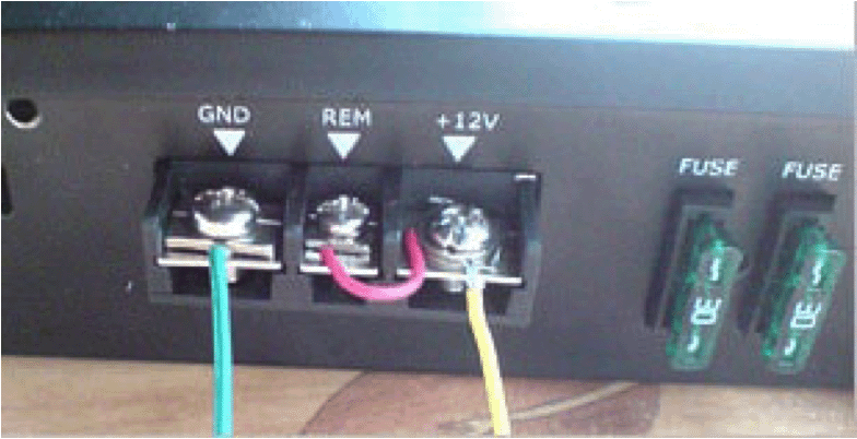
The remote turn on wire receives a voltage signal from your vehicle's electrical system when the ignition is turned to the Accessory or On position. When the amplifier senses this voltage at its remote turn on terminal, it powers up. When the ignition is switched off, that voltage disappears and the amplifier shuts down.
If the wire is connected to a constant power source, your amp will never shut off. If it's connected to something that never receives voltage when the ignition is on, the amp will never turn on. Getting this right is the foundation of a clean, reliable install.
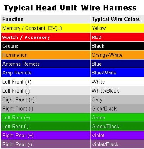
Note: Most wiring harnesses include two blue wires — one solid blue (for power antenna or factory amp turn-on) and one blue with a white stripe (the actual remote turn on). Don't mix these up.
Wiring Remote Turn On with an Aftermarket Head Unit
If you're installing an aftermarket head unit, this is the easiest scenario. Your new radio's wiring harness will have a clearly labeled blue/white wire. Simply connect a run of blue primary wire to it and route it back to your amplifier's remote turn on terminal. Use an appropriately sized butt connector to join the wires cleanly.
If you need wire or connectors for this step, MTX carries speaker, ground, and power wire as well as fuseholders, terminals, and connectors to get the job done right.
Wiring Remote Turn On with a Stock / Factory Head Unit
Factory radios don't have a dedicated remote turn on output, so you'll need to tap into a part of the vehicle's electrical system that only receives voltage when the ignition is on. The most reliable option is the vehicle's fuse box — find a fused circuit that is ignition-switched (such as the radio fuse) and tap into it. Since the remote turn on draw is very low current, it can share almost any ignition-switched fuse without issue.
Before connecting anything: use a multimeter to confirm the wire you've chosen only receives voltage with the ignition on. This 30-second check prevents the most common remote turn on mistake.
Since the factory wire is terminated on both ends, you'll need to splice into it. Use a T-tap connector, or cut the wire and use a butt connector to join all three wire ends — the two cut factory wire ends and your new remote turn on wire. Wrap every connection in electrical tape or heat shrink tubing to protect against moisture and vibration.
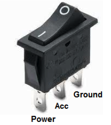
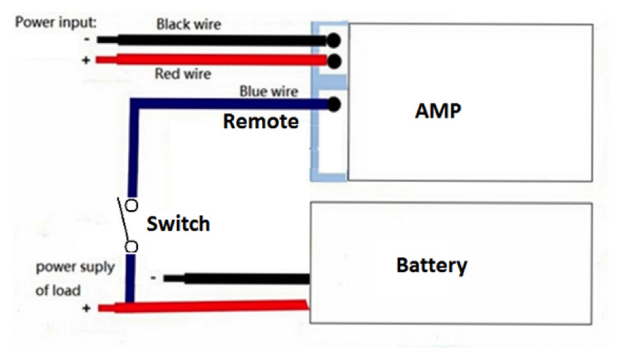
Wiring Remote Turn On to a Switch (UTV, ATV, Off-Road)
For powersports and off-road installs — UTVs, ATVs, side-by-sides — it's common to wire the remote turn on to a rocker switch rather than the ignition. Wire constant power and ground to the switch, then run the switch output to the amp's remote turn on terminal. This gives you manual control over when the system is on.
The main risk: if you leave the switch on when the vehicle isn't running, the amp will draw power and can drain the battery. Just make it part of your shutdown routine.
If you're building out a powersports audio system, MTX has purpose-built powersports audio including weather-resistant amplifiers and vehicle-specific solutions for Polaris RZR, Can-Am, and more.
How to Test Your Remote Turn On Wire
Once wired, or any time you suspect a remote turn on issue, you can verify it quickly with a multimeter:
- Place the positive multimeter lead on the remote turn on wire strands (touching the bare wire, not the jacket). Place the negative lead on a solid ground point.
- Ignition OFF — you should read 0 volts. Any voltage here means the wire is connected to a constant power source.
- Ignition ON — you should read 12+ volts. No voltage here means a bad connection or the wrong wire was tapped.
How to Splice Into Existing Wiring
There are three common methods for splicing into vehicle wiring, ranging from most durable to most convenient:
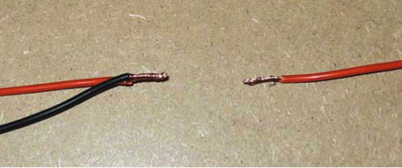
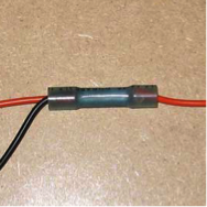
Solder + heat shrink — The best and most durable connection. Strip both wires, twist together, solder the joint, then cover with heat shrink tubing. Takes the most time but provides the most reliable long-term connection.
Butt connectors — A reliable and widely used method. Cut the existing wire where you want to splice in, crimp one cut end into one side of the butt connector, then insert your new wire along with the other cut end into the open side and crimp. Wrap in electrical tape or heat shrink when done. MTX carries a range of fuseholders, terminals, and connectors in sizes to match your wire gauge.
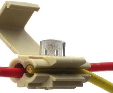
Scotch locks (T-taps) — The quickest option since they don't require cutting. However, they're the least reliable — the internal blade doesn't always pierce the wire insulation fully. Always test continuity with a multimeter after using one.
Two Things You Should Never Do
Don't jumper the power terminal to the remote turn on terminal. This is a common shortcut when an amp won't turn on, but it means the amp will never shut off — it will draw from the battery constantly, even with the vehicle off. That's a dead battery waiting to happen.
Don't use the power antenna wire in newer vehicles. In older vehicles, tapping the power antenna for remote turn on worked fine. In newer vehicles, the power antenna circuit is often only active in AM/FM mode — the moment you switch to Aux, Bluetooth, or satellite radio, the antenna wire loses power and your amp shuts off mid-listen.
Ready to Build Your System?
Here's where to go next on MTX.com:
- Shop MTX Car Amplifiers — Mono, 2-channel, 4-channel, and multi-channel amps across every series
- Amplifier Wiring Kits — Everything you need for power, ground, signal, and remote in one kit
- Fuseholders, Terminals & Connectors — Butt connectors, T-taps, ring terminals, and more
- Speaker, Ground & Power Wire — Primary wire in the gauges you need
- Subwoofer + Amplifier + Enclosure Packages — Ready-to-install bundles that take the guesswork out of system matching
- Powersports Audio — If you're installing in a UTV, ATV, or side-by-side
- Marine Amplifiers — Weather-resistant amps built for boat installs