The purpose of a loudspeaker is to move air. The most common system for achieving this is the electrodynamic driver — a diaphragm set in motion by an electromechanical motor system. Understanding how that motor system works, what controls its performance, and how power handling is measured and defined gives you a significant advantage when selecting and matching components.
Driver Components
An electrodynamic driver is composed of four systems:
- Motor: Voice coil, pole piece, front plate, back plate, magnet
- Diaphragm: Cone, dust cap
- Suspension: Spider, surround
- Basket / Frame
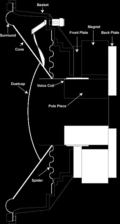
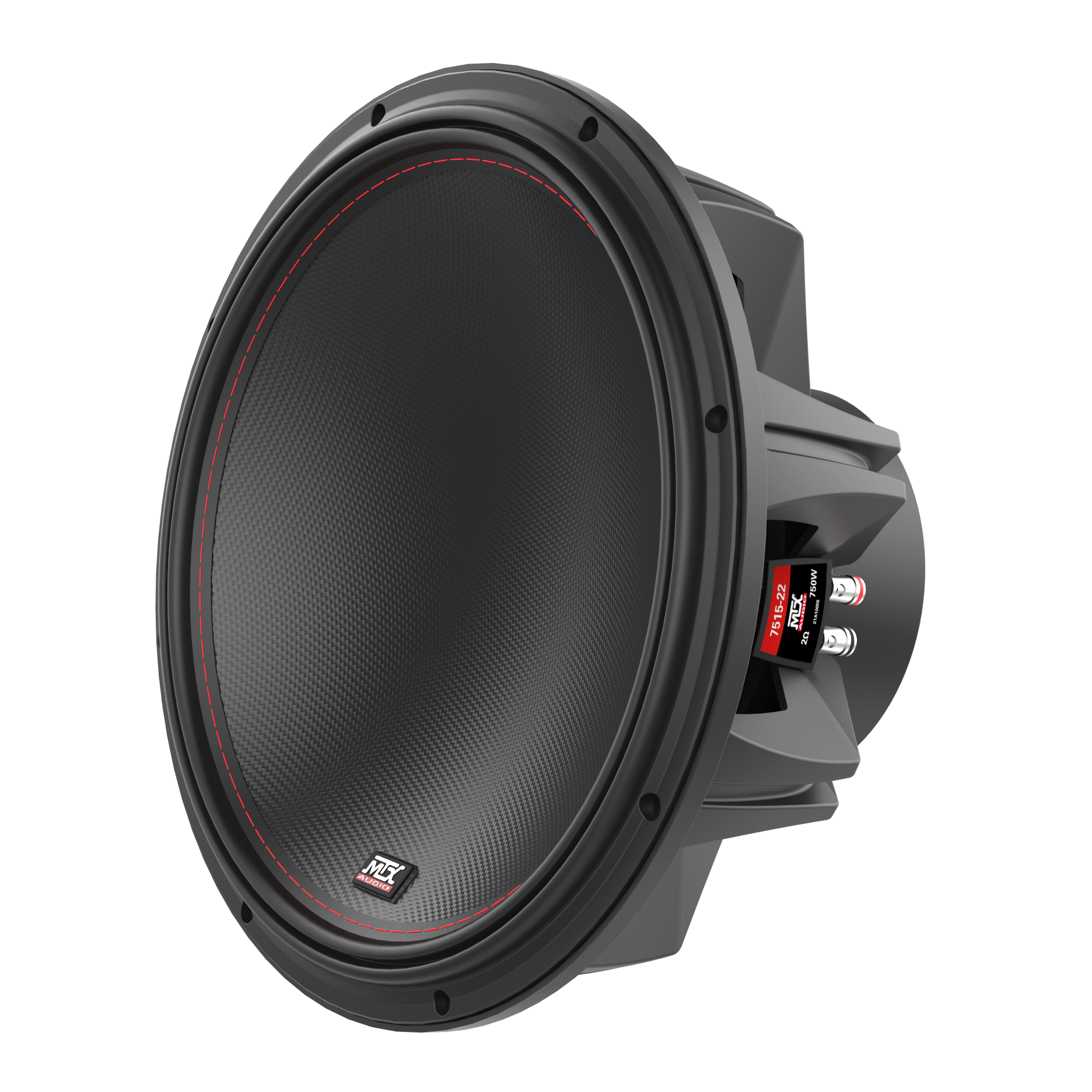
The speaker's motion comes from its motor system: a magnetic circuit and a voice coil. The voice coil gap is the small air space between the top edge of the pole piece and the inside edge of the front plate. The voice coil sits centered within this gap — thin strands of wire wrapped around a former that supports the coil and aids in transferring heat away from the gap. When current passes through the coil, magnetic forces push it against the gap's field. The direction of travel depends on the direction of current flow.
The inside edge of the cone attaches to the voice coil former. The cone physically moves the air — its shape, weight, and material directly affect frequency response. The dust cap covers the voice coil assembly and keeps foreign particles out of the gap. It also contributes to frequency response.
The spider connects the voice coil former to the basket, centering the voice coil and providing a restoring force. The surround seals the cone to the basket and adds to that restoring force while absorbing flexure waves as they travel up the cone. The basket, typically stamped steel or cast aluminum, does not directly affect sound but is critical for aligning the voice coil within the magnetic circuit. A bent basket causes the voice coil to rub against the gap walls, resulting in immediate failure.
Thiele/Small Parameters
The works of Neville Thiele and Richard Small are considered the most significant contributions to loudspeaker design methodology. Their research produced a method for predicting the frequency response of a loudspeaker system based on measurable physical characteristics.
Physical characteristics:
Response parameters derived from the above:
By understanding the relationship between these parameters, engineers can alter the response of a driver to meet specific design goals. The formulas that calculate predicted frequency response are complex and best handled by software. Several quality enclosure design programs automate this process.
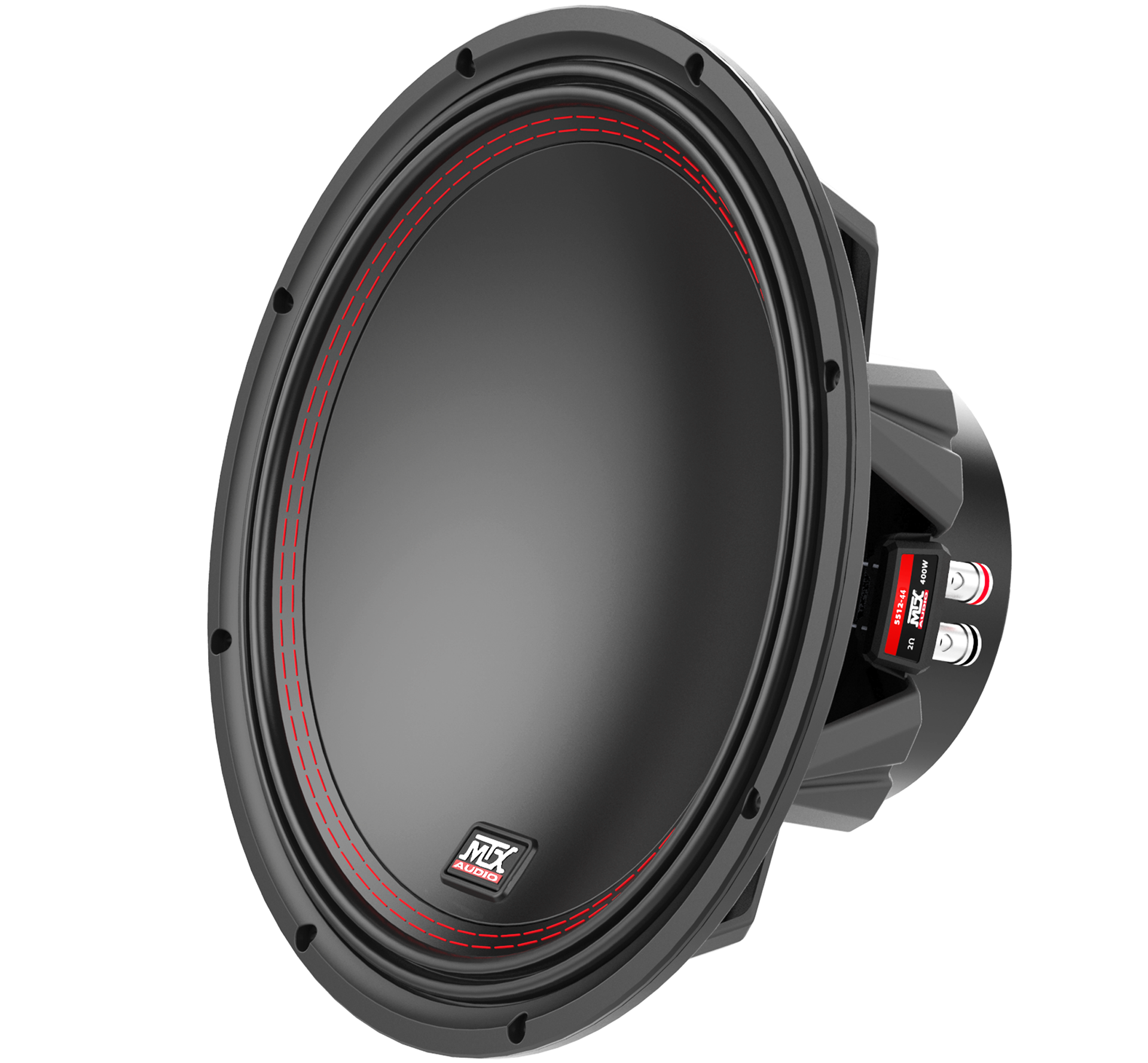
Excursion and Xmax

How loud a speaker can play is determined by how much air it can move without overheating. That is a function of cone surface area and the excursion capability of the motor system.
Xmax is defined as the width of the voice coil that extends beyond the front plate, plus 15%. It represents how far the speaker can move in either direction without appreciable distortion. The amount of power required to drive a speaker to its maximum excursion is called the displacement limited power handling — a number that varies with enclosure size and frequency.
Power Handling: What the Numbers Actually Mean
Speaker power handling is one of the most commonly quoted and most poorly understood specifications in the industry. Marketing departments consistently find ways to publish higher numbers, making it difficult to compare products or understand how ratings translate to real-world performance. Loudspeakers fail in one of two ways:
Mechanical failure: Surround, spider, or cone becomes fatigued, tears, or breaks from prolonged high-excursion use.
Thermal failure: Heat from electrical power dissipated in the voice coil causes adhesives to break down, wire insulation to fail, shorted turns, or the coil former to melt or burn.
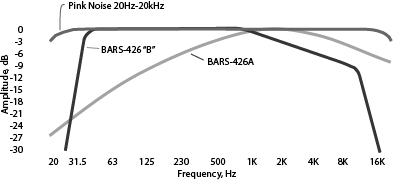
MTX tests loudspeakers using pink noise band-limited from 20Hz to 20kHz with a crest factor limited to 6dB (four-to-one peak to average power ratio). Drivers are tested in free air without an enclosure for eight hours and must pass without permanent change in performance. This is a conservative test that produces realistic ratings and allows direct comparison across product lines.
Because the speaker is tested in free air without an enclosure adding suspension stiffness, and the test signal contains full power down to 20Hz, this is mechanically severe. Voice coil excursions must quadruple for every halving of frequency to produce the same acoustic output, so surrounds and spiders are pushed to their maximum. Most failures in this test are mechanical rather than thermal.
Many manufacturers use the EIA standard RS-426A, which applies a white noise signal band-limited from 40Hz to 318Hz. When displayed on an RTA, this signal has a bandwidth from approximately 500Hz to 8kHz with a peak near 2kHz — meaning relatively little low-frequency content. Because the signal is centered around 2kHz where most woofers have impedance two to three times their nominal value, the actual power delivered is far less than the calculated figure suggests. The result is unrealistically high power handling ratings that do not reflect actual usage conditions.
MTX has adopted a proposed revision of EIA RS-426 as an internal standard. The test signal has a flat response from 40Hz to 1kHz, with a 3dB per octave rolloff from 1kHz to 10kHz, and rapid rolloff above 10kHz and below 40Hz. This stresses drivers both mechanically and thermally to nearly equal degrees using a signal that closely represents real music. The resulting ratings give buyers a realistic picture of what amplifier power can be safely used with a given speaker.
MTX defines "RMS power" as the power a speaker withstands under these test conditions. "Peak power" is retired in favor of "total power," defined as a maximum of four times the RMS rating — reflecting the 6dB crest factor of the test signal, which corresponds to a power ratio of four.
The correct power and frequency limits for a specific driver and enclosure combination depend on the build. MTX support can help with recommendations for your specific drivers and enclosures.
Contact MTX support or find an authorized dealer near you.
Frequently Asked Questions
Recommended Reading
For those who want to go deeper into loudspeaker theory and enclosure design: